

7 Marine VHF Antenna Installation Steps for Maximum Range

Last Updated: October 25, 2026
Quick Summary
Marine VHF antenna installation for maximum range starts with selecting the right antenna by gain rating, then mounting it as high as possible with clear line-of-sight to the horizon, since antenna height above water determines your maximum possible range far more than antenna length or gain.
- Antenna gain ratings range from 6dB for compact antennas to 10dB or higher for larger vessels, but height matters more than gain for achieving range.
- The radio horizon formula Range ≈ 1.23 × (√h1 + √h2) in nautical miles lets you calculate maximum range before installation based on antenna height above water.
- Mount the antenna at a hardtop corner, mast, or radar arch with clear line-of-sight in all directions, avoiding metal structures and obstacles that block signals.
- Use stainless steel hardware, marine-grade sealant, low-loss coaxial cable, and waterproof connector boots to prevent corrosion and signal loss.
- Test continuity with a multimeter, verify the antenna is vertical, and conduct a structured radio check to confirm proper installation before relying on the system.
Table of Contents
- Step 1: Choose the Right Antenna for Your Boat and Radio
- Step 2: Select the Optimal Marine VHF Antenna Mounting Location
- Step 3: Understand Antenna Height and Line-of-Sight Range
- Step 4: Install the Mounting Bracket and Hardware
- Step 5: Route and Terminate Marine VHF Antenna Cable and Connectors
- Step 6: How to Test a Marine VHF Antenna After Installation
- Verify Your Installation and Start Transmitting
- Frequently Asked Questions
Step 1: Choose the Right Antenna for Your Boat and Radio
The antenna's gain rating, measured in decibels (dB), determines how far your signal travels.
Smaller boats with limited mounting height benefit from compact 6dB antennas; larger vessels can support taller 14-foot or 16-foot antennas with higher gain. Learn more about marine VHF radio fundamentals before finalizing your choice.
At Charleston Yachting, we stock professional-grade antennas that deliver consistent performance.
Check your radio's specs: most modern VHF radios accept standard 1-inch-14 threaded connectors and are rated at 25 watts for recreational use.
Cable quality matters as much as the antenna itself. Low-loss coaxial cable preserves signal strength over longer runs.
Step 2: Select the Optimal Marine VHF Antenna Mounting Location
Mounting location determines your antenna's effectiveness more than any other factor.
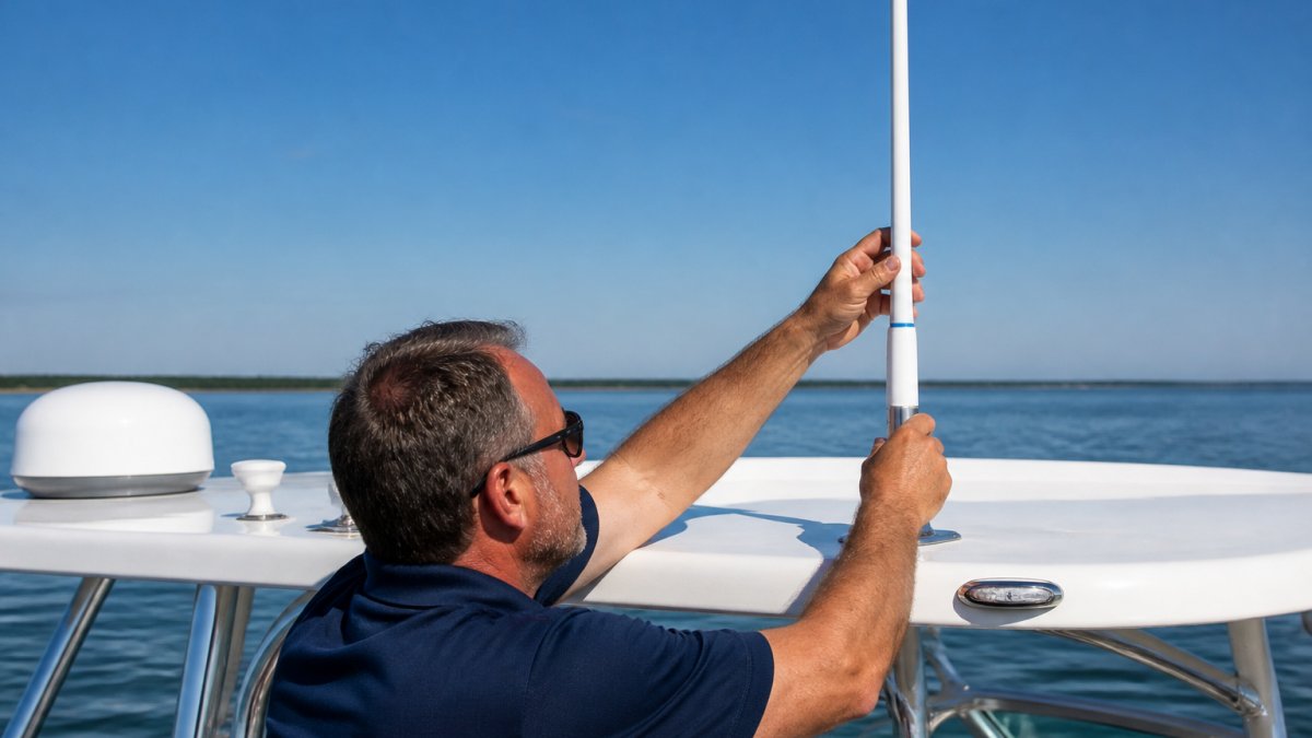
Height is your first priority: radio waves travel in straight lines and cannot bend around the earth's curve, so height creates range.
Avoid metal structures that block signals, railings, radar domes, and cabin tops create dead zones.
Common mounting locations include:
- Hardtop or T-top rear corners
- Mast on sailing vessels
- Radar arch on larger boats
Water proximity helps: antennas near the water's edge gain slightly extended range from the water's reflective properties, an advantage mast-mounted sailboat antennas achieve naturally.
Step 3: Understand Antenna Height and Line-of-Sight Range
Antenna height above the water, not antenna length, sets your maximum possible range. VHF signals travel in essentially straight lines, so the radio horizon is a geometry problem you can calculate before drilling a single hole.
The line-of-sight formula
A widely used approximation for the radio horizon over water:
Range in nautical miles ≈ 1.23 × (√h1 + √h2)
where h1 is your antenna height above the water in feet and h2 is the other station's. The 1.23 factor accounts for typical VHF refraction over water. It is an estimate, atmospheric ducting can extend it; rain, sea state, and terrain can cut it, but far more useful than a rule of thumb tied to antenna length.
Worked examples
- Your antenna 10 ft above water, other boat 10 ft: 1.23 × (√10 + √10) ≈ 1.23 × 6.32 ≈ 7.8 nautical miles maximum.
- Your antenna 10 ft, other boat 3 ft (a handheld at deck level): 1.23 × (√10 + √3) ≈ 1.23 × (3.16 + 1.73) ≈ 6.0 nautical miles.
- Your antenna 30 ft (masthead on a sailboat), other boat 10 ft: 1.23 × (√30 + √10) ≈ 1.23 × (5.48 + 3.16) ≈ 10.6 nautical miles.
The numbers show it: going from 10-foot to 30-foot mounting height roughly doubles range to a given station, while swapping a 6 dB antenna for a 9 dB one at the same height changes range far less. Height wins, the Step 2 mounting decision matters more than the gain rating on the box.
What gain actually does
Antenna gain does not bend the signal around the earth's curve; it flattens the radiation pattern toward the horizon. A high-gain antenna on a sailboat heeling 20 degrees can point part of its pattern into the water or sky, which is why many offshore sailors prefer moderate gain at the masthead over very high gain at deck level. Match gain to your boat's motion and mounting height, not a marketing number.
Realistic expectations
A 25-watt fixed-mount VHF with a well-installed antenna at 10 feet typically talks ship-to-ship at 5 to 8 nautical miles and to a tall shore station at 15 to 25. If you get only 2 miles to a nearby boat with a similar setup, you have an installation problem, cable loss, a bad connector, or poor ground, not a height problem. Use the formula to set expectations, then confirm with the Step 6 tests.
Vertical polarization still matters: keep the antenna as vertical as your mount allows, since a tilted antenna loses efficiency regardless of height. But don't let polarization push you into a lower mounting position, height is the dominant variable.
Step 4: Install the Mounting Bracket and Hardware
The mounting bracket secures your antenna to the boat.
Most marine VHF antennas use a standard 1-inch-14 threaded base, which mounting brackets accept.
Get the antenna mount bracket you need to complete your installation properly.
Digital Antenna 16' VHF Antenna - White [532-VW-S] →
Steps for bracket installation:
- Select the mounting location you identified earlier
- Drill or prepare the mounting surface per bracket instructions
- Use stainless steel bolts, washers, and lock washers
Let sealant cure fully, most marine sealants need 24 hours, to prevent water infiltration that causes corrosion and signal loss.
Check bracket alignment again after curing. Vibration and curing sometimes shift alignment slightly. Your antenna must remain vertical.
Step 5: Route and Terminate Marine VHF Antenna Cable and Connectors
Cable routing protects your signal and your boat.
Clean electrical terminals before connecting antenna cables to ensure optimal conductivity and signal transmission.
Connector types matter. Match your connector type to your radio. Get the correct connectors for your cable termination.
Termination steps:
- Strip 1 inch of outer jacket from the cable end
- Expose the inner conductor carefully
- Slide the connector body over the cable
Waterproofing is essential: salt spray corrodes exposed connections quickly, and electrical tape alone is insufficient.
Secure the cable with UV-rated cable ties and avoid sharp edges where it might rub.
Step 6: How to Test a Marine VHF Antenna After Installation
Testing proves a good installation and catches a bad one before you need it. Do this in order, and do not transmit on Channel 16 for a routine radio check, it is the distress, safety, and calling channel, and unnecessary transmissions there are discourteous and, in some areas, contrary to good operating practice. Use a working or dedicated radio-check channel instead.
1. Visual and mechanical inspection (power off)
- Confirm the antenna is vertical and the mount hardware is tight.
- Check that the connector is fully seated and the waterproofing boot or heat-shrink is intact.
- Look for any point where the coax is kinked, pinched, or rubbing against a sharp edge.
2. Continuity and short checks with a multimeter (power off, antenna disconnected from radio)
With the coax disconnected at the radio end:
- Center pin to shield: should read open (no continuity). A reading here means a short in the connector or cable.
- Center pin to center pin at the other end: should read continuity (near zero ohms). An open reading means a broken center conductor.
- Shield to shield at the other end: should read continuity. An open reading means a broken shield braid.
These three checks catch the most common termination mistakes, a stray braid strand touching the center pin, a cold solder joint, or a connector that was never fully seated.
3. SWR check where appropriate
If you have access to an SWR meter rated for VHF, or a technician who does, an SWR reading near 1.5:1 or lower across the marine band indicates a healthy antenna system. A reading above roughly 2:1 suggests a connector problem, cable damage, or a mismatched antenna. Do not transmit into a high-SWR load for extended periods; it can damage the radio's final amplifier.
4. Structured radio check
- Select a working channel or the local radio-check channel used in your area.
- Make a brief call: vessel name, "radio check," and the channel you are on.
- Ask for a signal report: readability and signal strength.
A useful pattern is to request a radio check from a station at a known distance, a marina, a tow service, or another vessel, and compare the result to the range you calculated in Step 3. If you are falling well short of the calculated range, treat it as an installation fault until proven otherwise.
5. Symptom-to-cause diagnosis
| Symptom | Likely cause | Corrective action |
|---|---|---|
| No transmit, no receive | Connector not seated, center pin shorted, cable open | Recheck continuity; re-terminate connector |
| Receive works, transmit weak or distorted | High SWR, damaged cable, poor ground | SWR check; inspect cable run; verify ground |
| Intermittent operation | Loose connector, corroded terminal, chafed cable | Reseat and waterproof; replace damaged cable section |
| Short range to nearby stations | Cable loss too high, wrong coax, antenna not vertical | Shorten run or upgrade coax; re-aim antenna |
| High background noise | Cable routed near electrical noise source | Reroute away from engine and electrical panels |
| Water in connector | Failed waterproofing | Dry, clean, re-terminate, and re-seal |
6. Document the baseline
Record antenna model, mounting height above water, coax type and length, connector type, and the results of your radio checks. This baseline is what lets you tell the difference between a normal seasonal change and a developing fault. Re-run the continuity checks and a radio check at the start of each season, and after any work that disturbs the cable run or mount.
Verify Your Installation and Start Transmitting
Your installation is complete when testing confirms reliable transmission and reception. Document your antenna type, height, cable length, and connector type to help troubleshoot future problems.
Schedule regular maintenance. Inspect connectors twice yearly for corrosion. Test transmission quarterly. Replace cable if you notice signal degradation.
Your marine VHF antenna installation now supports reliable emergency communication and routine maritime traffic. Proper installation delivers the range you need when you need it most.
Charleston Yachting stocks everything required for professional marine VHF antenna installation. Our same-day shipping gets your installation complete quickly. Shop all marine VHF antennas and installation hardware to find exactly what your boat needs.
Frequently Asked Questions
Does antenna height really affect marine VHF range?
Yes. VHF signals travel in a straight line and require line-of-sight contact between transmitter and receiver. Every foot of antenna height extends your practical range. A 14-foot antenna mounted on a hardtop reaches farther than the same antenna mounted lower on a cabin. Height matters more than raw antenna power; a high-mounted 6dB antenna often outperforms a low-mounted 10dB antenna. Even on smaller boats, mounting as high as your boat structure allows, typically 15 to 25 feet above water, noticeably improves both transmission and reception.
What's the best way to route marine VHF antenna cable to avoid signal loss?
Use low-loss coaxial cable (RG-8/X or better) and keep the cable run as short as possible. Every 10 feet of standard cable introduces signal loss; longer runs require thicker, more expensive cable to compensate. Route the cable away from high-current wiring, engines, and radar to prevent electrical interference. Secure the cable with clips every 18 inches, keep it clear of moving parts, and seal all connections with waterproof tape or heat shrink. Most marine installations use 20 to 40 feet of cable; if yours exceeds 50 feet, upgrade to low-loss RG-8 or consider relocating the radio closer to the antenna.
How do I know if my marine VHF antenna installation is working correctly?
Perform a radio check on Channel 16 with another boat or a shore station. If they report clear audio and you receive their transmission clearly, your installation works. Check your antenna connector for corrosion or loose fittings, and inspect the cable for kinks or damage. You can also use a VHF antenna analyzer to measure impedance and ensure the antenna is tuned properly. A properly installed antenna should show an impedance near 50 ohms at 156.8 MHz. If you hear excessive static, your transmission cuts out at normal ranges, or others report weak audio, inspect cable connections, verify cable routing away from interference, and confirm the antenna height and mounting location meet installation guidelines.
What connectors should I use for a marine VHF antenna installation?
Most modern marine VHF antennas use either PL-259 (UHF) or FME connectors. Check your radio's input port and your antenna's factory connector before purchasing. PL-259 connectors are more common on larger vessels and professional installations; FME connectors are compact and popular on smaller boats. Ensure connectors are gold-plated or nickel-plated stainless steel to resist corrosion. Always use marine-grade connectors rated for saltwater environments. Pre-assembled cables with factory-installed connectors eliminate field soldering and reduce connection failures; the Shakespeare Galaxy 5230 and Digital Antenna 16' VHF Antenna both ship with compatible connectors and low-loss cable ready to install.
Installing a marine VHF antenna for maximum range requires attention to antenna selection, mounting location, cable quality, and verification testing. The steps outlined here follow professional installation practices. Your communication reliability depends on getting each step right. Charleston Yachting's premium antenna selection and marine electronics inventory ensure you have the quality components needed for a successful installation that performs when it matters most.
