

How to Integrate Marine Electronics: 2026 Guide

Table of Contents
- Step 1: Map Your Network Architecture and Choose a Protocol
- Step 2: NMEA 2000 Network Setup From Backbone to Terminators
- Step 3: Gather Your Marine Electronics Installation Tools
- Step 4: Cable Routing, Waterproof Connectors, and Labeling
- Step 5: Bridge Legacy Systems With Gateways and Firmware Updates
- Garmin vs B&G Marine Navigation Systems: Which Ecosystem Fits Your Boat?
- Common Integration Mistakes and How to Avoid Them
- Conclusion
- Frequently Asked Questions
Last Updated: September 14, 2026
Step 1: Map Your Network Architecture and Choose a Protocol
Learning how to integrate marine electronics starts with one decision: which network protocol your devices speak. Get this wrong and you'll spend a season chasing gremlins instead of fishing.
NMEA 2000 is a controller area network (CAN) bus standard that lets navigation devices share data over a single backbone cable with standardized connectors (NMEA 2000 Standards - National Marine Electronics Association (NMEA)). NMEA 0183 is the older serial standard, sending one-way data over dedicated wires between two devices.
Most boats built in the last two decades run a mix of both. Your chartplotter, autopilot, AIS, radar, and multifunction display may all support NMEA 2000, while an older transducer or VHF radio may only output 0183 sentences. According to the NMEA standards overview from the National Marine Electronics Association, the two protocols coexist on most refits, which is why gateways matter.
NMEA 2000 vs NMEA 0183: What Your Devices Actually Speak
A common mistake is assuming "NMEA compatible" means plug-and-play. It doesn't.
| Feature | NMEA 2000 | NMEA 0183 |
|---|---|---|
| Topology | Single backbone, drop cables | Point-to-point wiring |
| Data direction | Bidirectional | Mostly one-way |
| Connectors | Sealed, standardized | Bare wire, terminal blocks |
| Best for | Multi-device networks | Legacy single-device links |
| Typical fix | T-connector + drop cable | Gateway or converter |
If a device only lists 0183 output, plan on a converter. If it lists 2000, you're on the backbone.
Step 2: NMEA 2000 Network Setup From Backbone to Terminators
A NMEA 2000 network setup follows five fixed rules: one backbone, two terminators, one power node, drop cables under 6 meters, and no closed loops (nmea.org). Break any and the bus may still "work" until it doesn't.
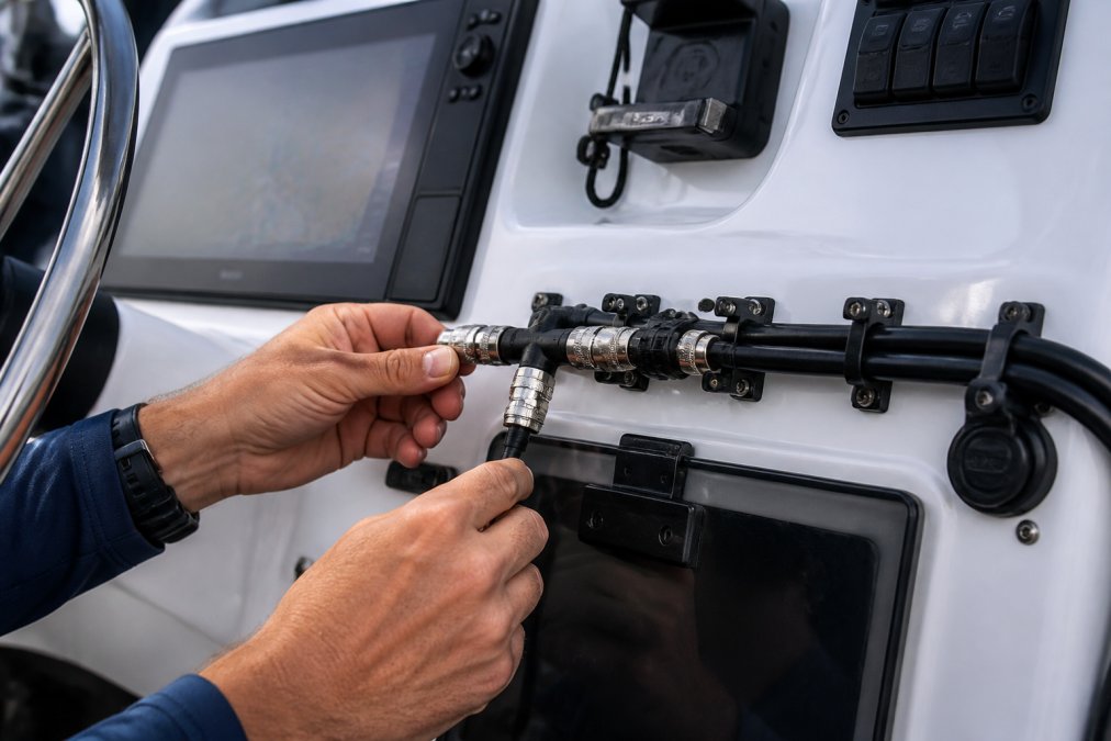
Run the backbone as a single trunk from bow to stern. Each device taps in through a T-connector and drop cable. Cap both ends with 120-ohm terminators. The power node belongs near the middle of the bus, not at one end.
For small networks, a self-contained block simplifies this considerably. The Actisense Self-Contained Boat Network replaces eight T-pieces with one unit, with internal terminators and power feed built in.
![Actisense Self-Contained Boat Network - Complete Network f/8 Devices w/Internal Terminators Power Feed [A2K-SBN-2]](https://cdn.shopify.com/s/files/1/0842/4914/9751/files/83394XL.jpg?v=1775846215)
Power Distribution, Fusing, and Voltage Drop
Voltage drop is the silent killer of marine networks. On a 12V system, a 1V drop at the far end of a long backbone can push devices below their minimum operating voltage, causing dropouts that look like firmware bugs.
Size your backbone cable for the total load and length, not just the nearest device. Fuse the power feed at the source, close to the battery or distribution panel, with a marine-grade fuse rated to the bus load. Fusing at the far end protects nothing.
Step 3: Gather Your Marine Electronics Installation Tools
The right marine electronics installation tools save hours and prevent rework. You don't need a full shop, just the right basics.
- Marine-grade heat-shrink crimp connectors (adhesive-lined)
- Ratcheting crimper sized for your connector gauge
- Digital multimeter with continuity and DC voltage
- Cable pull rods or fish tape for routing through conduits
- Dielectric grease for every sealed connection
- Zip ties and adhesive cable mounts
- Label maker or numbered heat-shrink labels
- Torque wrench for antenna and transducer mounts
Skip the automotive crimpers. They crush marine connectors and create the exact corrosion path you're trying to avoid.
Step 4: Cable Routing, Waterproof Connectors, and Labeling
Route cables high and dry, away from bilge water, fuel lines, and heat sources. Every bulkhead penetration needs a grommet or gland, and every splice should be crimped and heat-shrunk, never twist-and-tape.
Waterproof connectors matter more than most owners realize. NMEA 2000 uses sealed, keyed connectors that resist spray and humidity. NMEA 0183 and power feeds rely on you to seal the joint. Dielectric grease on every pin, adhesive heat-shrink over every crimp.
Label both ends of every cable, not just at the device. A label at the panel that says "AIS" saves an hour the next time you're upside down in a locker chasing a fault.
Step 5: Bridge Legacy Systems With Gateways and Firmware Updates
Gateways keep working equipment alive. A gateway translates data between NMEA 0183 and NMEA 2000, so an older GPS or VHF can feed your modern chartplotter without a full replacement.
The Actisense NMEA 0183 to NMEA 2000 Gateway with WiFi handles bidirectional conversion and pushes data to a laptop, tablet, or phone over Wi-Fi. For Nexus-to-Garmin conversions, the Garmin GND 10 Black Box Bridge does the same job within the Garmin ecosystem.
![Garmin GND 10 Black Box Bridge [010-01226-00]](https://cdn.shopify.com/s/files/1/0842/4914/9751/files/51105XL.jpg?v=1775842742)
Firmware Update Management: The Step Most Guides Skip
Firmware is the most common cause of a device that powers on, appears on the network, and still refuses to share data. Mismatched firmware between a chartplotter and a display, or a gateway and the bus, produces exactly the symptoms owners blame on bad wiring. Before troubleshooting anything, check every device's firmware version against the manufacturer's current release.
Interrupting a firmware write mid-flash can leave a device unresponsive, the "brick" scenario. A disciplined sequence prevents it.
- Inventory first. Write down every device on the bus, its current firmware version, and its model number. Photograph each version screen. You cannot roll back what you did not record.
- Update the gateway or bridge first. Gateways sit between protocols; updating them before the devices they translate keeps the translation layer stable while downstream devices change.
- Update one device at a time. Never flash two devices simultaneously, even on separate circuits. A shared power bus can dip during a flash and corrupt both.
- Hold steady power. Connect to shore power or a charged battery bank. A voltage sag during a write is the most common brick cause. Do not update on a weak battery.
- Do not power down until the device confirms completion. Some units reboot twice and appear frozen. Wait for the on-screen or LED confirmation, not your patience.
- Verify on the network. After each update, confirm the device still appears on the bus and still shares data before moving to the next one.
- Keep a rollback note. Record the version you started from. If a new release breaks integration, you have a documented path back.
Mobile App Integration for Remote Monitoring
Most integration guides stop at the helm. The bigger win is getting your network onto a tablet or phone. Gateways with built-in Wi-Fi, like the Actisense unit above, broadcast NMEA data to a mobile app without a separate router, so you can watch depth, speed, wind, and battery voltage from anywhere on the boat, or the dock if the gateway stays powered. Expanding this mobile visibility often reveals the necessity of integrating new equipment into your existing legacy architecture to ensure seamless data flow across every onboard system.
The trade-off is bandwidth and security. NMEA 2000 data is lightweight, but streaming chart and radar overlays over Wi-Fi can saturate a cheap access point. Keep the mobile link for monitoring and instrument data, not primary navigation, and change the gateway's default Wi-Fi password before you leave the dock; an open marine network is an open door.
Garmin vs B&G Marine Navigation Systems: Which Ecosystem Fits Your Boat?
The Garmin vs B&G marine navigation systems question usually comes down to sailing versus power, and how much of the boat you plan to network.
Garmin's ecosystem is broad, with strong chartplotter, radar, and autopilot integration and many compatible transducers. B&G leans toward sailing-specific instrumentation, with racing-oriented displays and wind data for performance sailors. Both support NMEA 2000, so either talks to third-party devices, but staying inside one ecosystem reduces gateway complexity.
If your boat is already wired for one brand, adding to it is almost always cheaper than switching. If you're starting fresh, pick the ecosystem that matches how you actually use the boat.
Common Integration Mistakes and How to Avoid Them
Integration failures cluster around a handful of repeatable errors. Fix these before adding another device.
- Missing or doubled terminators. Exactly two, one at each end of the backbone.
- Drop cables over 6 meters. Long drops cause voltage and signal problems.
- Power node at the end of the bus. Move it to the middle.
- Closed loops. A backbone must never form a ring.
- Unlabeled cables. You will forget what you wired last season.
- Skipped firmware updates. Update before you diagnose.
- Mixed connector types without adapters. Forcing a fit damages pins.
Voltage Drop: The Math Behind the Mistake
Voltage drop is the error that hides best. On a 12V system, current through a long, undersized backbone cable loses voltage to resistance. A 1V drop at the far end can push a device below its minimum operating voltage, producing dropouts that look exactly like firmware bugs or a dead device.
The relationship is simple: drop rises with current and cable length, and falls with larger wire gauge. Doubling the run doubles the drop; doubling the wire cross-section roughly halves it. That is why a backbone sized for two devices at the helm fails when you add a stern-mounted display thirty feet away.
A practical rule most installers follow: size the backbone for the total load and full run length, not the nearest device. Measure voltage at the last device while the bus is active, not at the power node. If it reads below 11.5V under load, upsize the feed cable or shorten the run before adding another device. Fuse the power feed at the source, close to the battery or distribution panel, with a marine-grade fuse rated to the bus load.
A Diagnostic Flow That Actually Narrows the Fault
When a device does not appear on the network, work in order and stop at the first failure:
- Power at the device. Confirm DC voltage at the device connector, not at the panel.
- Drop cable and T-connector. Reseat, then swap with a known-good drop.
- Terminators. Confirm exactly two, one at each end, both 120-ohm.
- Backbone continuity. Check for a broken trunk or a closed loop.
- Firmware version. Compare against the manufacturer's current release.
- Gateway translation. If the device is 0183 and the network is 2000, confirm the gateway is passing the sentence you need.
Most "dead" devices pass the first three checks and fail at the firmware or gateway step. That is why updating firmware before diagnosing saves hours.
DIY vs Professional: When to Call In Help
Not every integration is a DIY project. Use this threshold to decide:
- Stay DIY: Adding a device to an existing, working NMEA 2000 backbone. Swapping a drop cable. Updating firmware. Labeling and documenting an existing network.
- Consider professional help: Building a new backbone from scratch, running cable through sealed bulkheads or a cored hull, integrating radar or autopilot with a chartplotter across brands, or diagnosing an intermittent fault that survives the diagnostic flow above.
- Call a professional: Any work that requires drilling below the waterline, replacing a through-hull transducer, or commissioning a new autopilot or radar system. These carry warranty and safety implications that outweigh the labor savings.
The honest test: if you cannot explain how the device will get power, how it will join the network, and how you will verify it works before you buy it, the project has outgrown DIY.
Conclusion
Integrating marine electronics rewards planning over parts-buying. Map your architecture, respect the backbone rules, and label everything.
Charleston Yachting stocks the components this process depends on, from Digital Yacht NMEA 2000 Starter Cable Kits to gateways and network blocks, with same-day shipping and premium rigging and hardware from Garmin, B&G, and Harken. Get the network right the first time and spend your season on the water, not in the locker.
![Digital Yacht NMEA 2000 Starter Cable Kit [ZDIGN2KIT]](https://cdn.shopify.com/s/files/1/0842/4914/9751/files/67952XL.jpg?v=1775844545)
Frequently Asked Questions
What is the difference between NMEA 0183 and NMEA 2000?
NMEA 0183 is an older serial protocol that sends data point-to-point over small wires, usually at 4,800 or 38,400 baud. NMEA 2000 runs over a single powered backbone using CAN bus technology, letting many devices share data at 250 kbps. Most new chartplotters, AIS units, and autopilots use NMEA 2000, while older radar and instruments often rely on 0183. A gateway like the Actisense WGX-1 converts between the two so both can coexist on one boat.
Do I need a backbone for my marine electronics network?
Yes, if you are running NMEA 2000. The backbone is the powered central cable that every device taps into through a T-connector and drop cable. It needs a power node, usually mid-backbone, and a 120-ohm terminator at each end. Skipping the backbone or daisy-chaining devices causes signal interference and dropped data. Kits like the Digital Yacht NMEA 2000 Starter Cable Kit give you the backbone, T-connectors, and terminators in one box.
Can I mix and match marine electronics brands on the same network?
Yes, NMEA 2000 is a certified standard, so a Garmin chartplotter, a B&G autopilot, and a Digital Yacht AIS can share data on the same backbone. The catch is proprietary features. Garmin's GND 10 bridge, for example, is needed to bring Nexus instruments into a Garmin network. Check the NMEA 2000 certification logo on each device and confirm the specific data sentences or PGNs you need before buying.
How do I troubleshoot common marine electronics integration issues?
Start with the physical layer: confirm both terminators are in place, the backbone is powered at 12 volts, and no drop cable exceeds 6 meters. Check voltage drop at the farthest device, since anything below 9 volts at the device end causes intermittent faults. Then verify firmware is current on every unit, because mismatched versions break PGN sharing. If a single device is silent, swap its drop cable and T-connector before assuming the unit failed.