

7 NMEA 2000 Setup Steps for Your VHF Radio in 2026

Quick Summary
A VHF radio NMEA connection lets the radio share GPS position and heading with your chartplotter over an NMEA 2000 backbone. Confirm your radio has an NMEA 2000 port before buying, and use a gateway only if it outputs NMEA 0183 alone.
- Check the radio's manual to confirm it has an NMEA 2000 port before buying.
- NMEA 0183 radios need a gateway to convert their data onto the NMEA 2000 backbone.
- Keep each drop cable under 6 meters, and use exactly two terminators on the backbone.
- Test the receive direction before the transmit direction when troubleshooting a faulty connection.
Table of Contents
- Check Your VHF Radio NMEA 2000 Compatibility Before You Buy
- NMEA 2000 vs NMEA 0183: Which Protocol Your Radio Needs
- Using an NMEA 0183 to NMEA 2000 Gateway When Your Radio Only Speaks 0183
- Planning the NMEA 2000 Backbone and Drop Cable Layout
- Step-by-Step VHF Radio NMEA 2000 Installation
- NMEA 2000 Network Troubleshooting for VHF Radio Data Problems
- Confirm Your VHF NMEA 2000 Setup Works Before You Leave the Dock
- Frequently Asked Questions
Check Your VHF Radio NMEA 2000 Compatibility Before You Buy
Last Updated: November 19, 2026
Before you order any hardware, confirm that your VHF radio can actually connect to an NMEA 2000 network. Not every radio model supports it. Compatibility depends on the exact model you own, so check the manufacturer's installation instructions for your radio. Charleston Yachting carries radios with built-in NMEA 2000 support, including the Icom IC-M510 EVO VHF w/NMEA 2000 at $799.95 and the Standard Horizon Quantum GX6000 at $599.99, so you can match your purchase to what your boat needs.
Check the radio's specification sheet and installation manual for three things: an NMEA 2000 port, the data it supports, and any accessories required. The Standard Horizon GX6000 listing, for instance, describes an integrated NMEA 2000 interface.
A common mistake is buying a radio based on its VHF features alone and discovering later that it cannot send GPS position to your multifunction display. Confirm the NMEA 2000 function before you commit.
NMEA 2000 vs NMEA 0183: Which Protocol Your Radio Needs
NMEA 2000 is a plug-and-play network standard that lets devices share data over a single shared backbone (NMEA 2000 Standards - National Marine Electronics Association (NMEA)). NMEA 0183 is an older serial standard that sends data point to point, one talker and one listener per wire (NMEA 0183 - National Marine Electronics Association (NMEA)). The two are not interchangeable, and that difference determines how your radio connects.
If your radio has an NMEA 2000 port, you can wire it straight into the backbone. If it only outputs NMEA 0183, you will need a gateway to convert its data before the network can use it. Check which protocol your radio and chartplotter each support, because a mismatch is one of the most frequent reasons an integration fails.
Using an NMEA 0183 to NMEA 2000 Gateway When Your Radio Only Speaks 0183
If your radio outputs only NMEA 0183, a gateway translates its serial sentences onto the NMEA 2000 backbone. The gateway is not a passive adapter, it is a small computer that parses incoming 0183 sentences, maps each one to a corresponding NMEA 2000 parameter group number (PGN), and broadcasts that PGN on the network. If the gateway has no mapping for a sentence, that data simply does not cross the bridge.
That mapping detail is where most integration plans fail.
Before you buy a gateway, get the radio's NMEA 0183 output list from its manual and compare it sentence by sentence against the gateway's supported translation table.
Wiring is the easy part.
Planning the NMEA 2000 Backbone and Drop Cable Layout
Build the network around a single backbone run, with drop cables branching to each device. Keep each drop cable short. A common reference point is the 6-meter drop limit cited in installation guidance, and the core setup rules are: one backbone, two terminators, one power node, drop cables under 6 meters, and no closed loops.
For a short extension, the Garmin NMEA 2000 Backbone Cable (2M) at $34.99 extends the trunk. Connect devices with the Bluewater NMEA 2000 T-Connector at $18.90. Before you buy cable, sketch the layout and total the lengths.
Step-by-Step VHF Radio NMEA 2000 Installation
Start by mounting the radio at the helm, then route the backbone past its location. Connect the radio's NMEA 2000 cable to a T-connector on the backbone, keeping the drop short. Confirm the network has exactly two terminators and one power node before energizing anything.
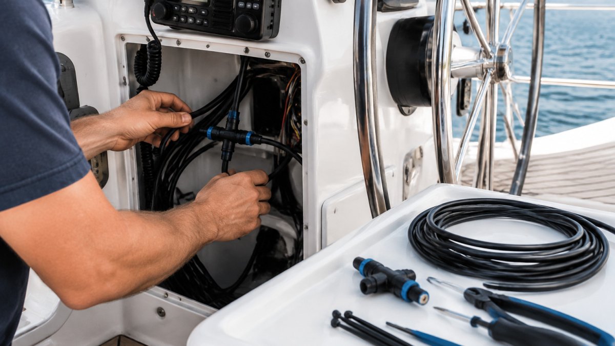
Work through these steps in order:
- Mount the radio and the optional speaker or remote microphone where they are accessible.
- Run the backbone and attach T-connectors at each device location.
- Connect the radio's drop cable to its T-connector.
- Power the network at a single power node.
- Power on the radio and confirm it receives GPS and heading data from your chartplotter.
Here is a wiring summary for reference:
| Component | Purpose | Installation Note |
|---|---|---|
| Backbone cable | Main network trunk | Single continuous run |
| T-connector | Branch point for a device | Keep drop under 6 meters |
| Terminator | Ends each backbone | Exactly two per network |
| Power node | Supplies network power | One per network |
| Gateway | Converts NMEA 0183 data | Only for 0183-only radios |
NMEA 2000 Network Troubleshooting for VHF Radio Data Problems
Troubleshoot in the order data flows, not in the order problems occur to you. A VHF radio on NMEA 2000 both consumes and produces data: it needs GPS position and heading from the network to make DSC calls, and it produces DSC and AIS traffic that the chartplotter displays. Test each direction separately, because a failure in one direction tells you nothing about the other.
Start at the physical layer. Confirm exactly two terminators are present, one at each end of the backbone, and that the backbone is not looped back on itself. A closed loop or missing terminator causes intermittent data loss that is hard to trace because the network may work at the dock and fail underway. Then confirm power: the network should have a single power node, and a device with insufficient voltage can appear connected but fail to transmit reliably. Check each connector for corrosion or a loose pin, since marine environments are harsh on connections.
Next, verify the network sees the radio at all. On most multifunction displays, the network device list or diagnostics page shows every device that has checked in, along with its source address. If the radio is absent from that list, the problem is physical or power, stop here and fix it before chasing data issues. If the radio appears but shows no GPS source, the problem is data routing, not wiring.
Then test the receive direction. Confirm the chartplotter is outputting a position PGN and that the radio has selected the network as its GPS source.
Test the transmit direction last. Place a DSC individual routine call to a known MMSI, your own second radio or a test contact, and confirm the chartplotter logs the call and any position report. If position data arrives but DSC traffic does not, the radio is receiving from the network but not transmitting to it, which points to a radio configuration or firmware issue rather than the backbone.
If the radio is connected through a gateway, verify that the 0183 sentences it sends are among those the gateway translates, and check the gateway's own status page for sentence counts. A gateway that shows zero translated sentences is misconfigured or wired to the wrong port, not broken.
Watch out: intermittent faults that appear only when the engine or a high-current load runs usually indicate a power or grounding problem, not a data problem. Check the network power node's voltage under load before you replace any cable.
Record what you find. A simple log of device list status, GPS source setting, and DSC test result at each step turns a future fault into a five-minute check instead of an afternoon of guessing.
Confirm Your VHF NMEA 2000 Setup Works Before You Leave the Dock
Before you cast off, test each function you plan to rely on. Confirm that the chartplotter displays the radio's GPS position, that a DSC test call completes, and that AIS targets appear where the radio supports them. Check that the speaker and microphone respond from every station.
Testing at the dock is far easier than troubleshooting offshore. Once everything passes, record your wiring layout so you can diagnose future problems quickly. Browse the marine electronics and NMEA 2000 cables in our catalog to find the parts for your network.
Frequently Asked Questions
How do you connect a marine VHF radio to an NMEA 2000 network?
Confirm the radio has a built-in NMEA 2000 port or an optional interface, then connect its drop cable to a T-connector on the backbone. Power the network from a dedicated circuit with a fused connection, and install one terminator at each end of the backbone. Once powered, the radio should appear on your chartplotter or multifunction display, where you can confirm that GPS position and DSC data are being received before you rely on it for calls.
Does a VHF radio need NMEA 2000 to use DSC?
No. DSC calling works on a standalone VHF radio using its own controls and an MMSI number programmed into the radio. NMEA 2000 adds the ability to pass GPS position data to the radio for DSC distress and routine calls, and to share AIS and DSC information with your chartplotter. Without a GPS input, you must enter your position manually, so an NMEA 2000 connection is useful rather than mandatory.
Can you connect an NMEA 0183 VHF radio to an NMEA 2000 chartplotter?
Yes, but only through an NMEA 0183 to NMEA 2000 gateway, which translates sentences into NMEA 2000 messages. Gateways do not convert every data type, so check which sentences your radio outputs and whether the chartplotter accepts them.
Why is my VHF radio not receiving GPS data from the chartplotter?
The most common causes are a missing terminator, a loose drop cable connector, a network that is not powered, or a radio model that cannot connect to NMEA 2000 at all. Check the radio's installation instructions, verify the backbone has two terminators, and confirm that the chartplotter is set to share GPS data on the network.
