

Troubleshooting Common Marine GPS Issues

Table of Contents
- Before You Start: What You'll Need
- Step 1: Check Power and Voltage Stability
- Step 2: Inspect Your Antenna and Connections
- Step 3: Troubleshoot Marine GPS Signal Loss Causes
- Step 4: Troubleshooting NMEA 2000 Network Issues
- Step 5: Software, Firmware, and Mobile App Fixes
- Step 6: When to Replace Hardware: Antenna and Puck Failure
- Common Mistakes to Avoid
- Frequently Asked Questions
Last Updated: September 26, 2026
Before You Start: What You'll Need
Marine GPS issues usually trace back to six things: power, antenna, signal, network, software, or hardware. This guide from Charleston Yachting walks through each in order.
Have on hand:
- A digital multimeter
- Dielectric grease and a small wire brush
- A soft cloth and fresh water
- Your chartplotter's manual or support page
- A phone or tablet with the manufacturer's app
- Zip ties and a spare NMEA 2000 drop cable
Step 1: Check Power and Voltage Stability
Start with power, because a weak supply causes most intermittent faults. A receiver that flickers on and off is usually starving for voltage, not failing outright.
Common causes:
- Corroded contacts on the fuse holder or breaker
- Undersized wire for the length of the run
- A loose ground connection at the bus bar
- A failing battery or charging system
Step 2: Inspect Your Antenna and Connections
The antenna and its cable cause more marine GPS signal loss than any other part of the system. Salt air, UV, and vibration work on connectors year after year.
Work through this checklist:
- Unplug and inspect every connector for green corrosion
- Check the center pin on coax fittings for damage or pushback
- Look for chafed or pinched cable along the run
- Confirm the antenna mount is tight and sealed
- Check that the antenna faces clear sky with no metal above it
Step 3: Troubleshoot Marine GPS Signal Loss Causes
Signal loss has two sources: something blocking the sky, or something interfering with the receiver. Both look identical on screen, so rule them out one at a time.
Obstructions and Environmental Interference
A GPS antenna needs a clear view of the horizon in all directions. Anything blocking that view slows satellite acquisition or kills it entirely.
Watch for:
- Radar arches, masts, and outriggers above the antenna
- A dodger or bimini shading the puck
- Dense tree cover or tall buildings
- Heavy rain, snow, or a wet antenna dome
Electromagnetic Interference from Other Electronics
Electromagnetic interference is the cause most boat owners never check. Radar, VHF radios, LED drivers, and even a cheap USB charger can drown out the weak GPS signal.
To test:
- Note signal strength with everything running.
- Switch off electronics one at a time.
- Watch for the signal bars to recover.
GPS.gov official GPS information
Step 4: Troubleshooting NMEA 2000 Network Issues
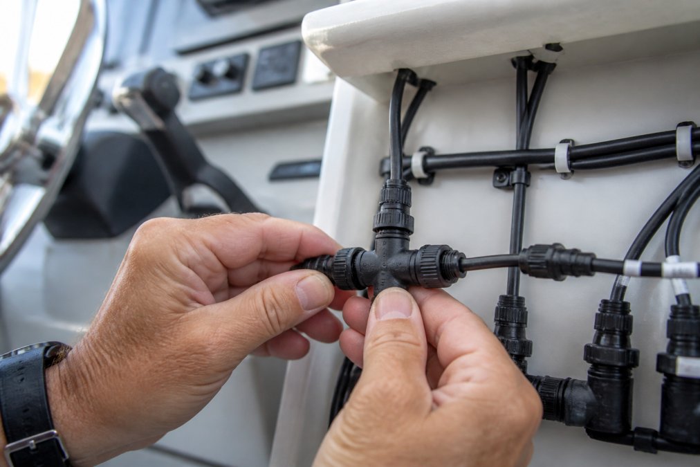
A GPS receiver that works fine alone but vanishes from your network is a data bus problem, not a satellite problem. NMEA 2000 networks carry position data to your chartplotter, autopilot, and instruments over a shared backbone, and a fault anywhere on it can look like a GPS failure.
Test Termination With a Multimeter
The fastest diagnostic on any NMEA 2000 network is a resistance reading across the backbone. Power down, then measure resistance between the CAN High and CAN Low pins at any open T-connector.
- A healthy, properly terminated bus reads approximately 60 ohms.
- A reading near 120 ohms means one terminator is missing or failed.
- A reading near 40 ohms means there are three terminators on the bus.
- An open or infinite reading means the backbone is broken or a terminator is disconnected.
Verify Backbone Power and Voltage Drop
NMEA 2000 specifies a nominal 12 VDC backbone, but the bus tolerates a range. Measure voltage between the network's power pins and ground at the furthest device from the power tap, not at the tap.
- Below roughly 9 VDC at the far end, devices start dropping off intermittently.
- A drop of more than about 1 VDC between the power tap and the furthest device points to an undersized backbone, a long run, or corroded connectors.
Check Drop Cables, T-Connectors, and Load
- Confirm every drop cable is under 6 meters; longer drops add capacitance and can corrupt the differential signal.
- Look for a loose T-connector, a bent pin, or a crimped drop cable instead of a proper field-installable connector.
- Count your devices. A single backbone segment supports a limited number of nodes; if you have added chartplotter, autopilot, AIS, instruments, and a GPS puck over the years, you may be near the practical limit and need a second backbone or a bridge.
Resolve Addressing and Device-Instance Conflicts
A device that appears in the network list but produces no data is usually an address conflict, not a wiring fault. NMEA 2000 devices claim a source address at startup, and two with the same device instance will fight for it, one wins, one goes silent.
Read the Diagnostic Screen Like a Technician
Your chartplotter's diagnostic screen tells you what the network already knows. Open the device list and look for the GPS unit's status.
| Symptom | Likely Cause | First Fix |
|---|---|---|
| Device missing from list | No power or bad drop cable | Reseat the T-connector, then measure backbone resistance |
| Device listed but no data | Wrong baud rate or address clash | Check device instance and preferred source |
| Data drops under load | Weak termination or voltage sag | Add or replace terminators; test far-end voltage |
| Position jumps around | Multipath error from reflections | Move the antenna |
| Whole bus drops when radar runs | Shared marginal supply | Give the backbone its own fused feed |
The Order That Saves Time
- Measure backbone resistance (should be ~60 ohms).
- Measure far-end voltage under load.
- Confirm drop cable lengths and connector condition.
- Check device instances and preferred source.
- Only then consider a factory reset on the GPS unit, it wipes your calibration, so do it last.
Step 5: Software, Firmware, and Mobile App Fixes
Software problems look like hardware problems until you update. A firmware update fixes known bugs, improves satellite tracking, and adds support for new satellite systems.
Follow this order:
- Back up your waypoints and routes first.
- Download the latest firmware from the manufacturer.
- Install it with the unit powered from a stable source.
- Reboot and confirm the version number changed.
- Recheck your position accuracy.
- The chartplotter and phone are on the same network
- Bluetooth pairing was cleared and redone
- The app has location permission enabled
- The unit's Wi-Fi is actually broadcasting
Step 6: When to Replace Hardware: Antenna and Puck Failure
Hardware does fail, and the signs are usually clear. An antenna puck that has taken on water will show erratic signal strength no matter what you do. The harder question is whether to replace the puck, the cable, or the whole receiver, and whether the money is better spent on a modern multi-band unit.
The Replace-vs-Repair Decision
Work through this in order. Stop at the first "yes."
- Did power and cable pass? If voltage is steady at the connector and the coax shows no corrosion, chafe, or center-pin damage, the fault is in the antenna or receiver.
- Is there visible water or a fogged dome? A puck with condensation inside has already failed. Replace it, do not try to dry it out.
- Is the housing cracked or the mount loose? Vibration and UV eventually win. Replace the puck and reseal the mount.
- Does the unit still fail in open sky with a known-good cable? The receiver is the problem. Replace it.
- Is the unit more than about a decade old? Even if it "still works," it may track fewer satellite systems than a current receiver. Replacement is often cheaper than the hours spent chasing intermittent faults.
What Actually Fails Inside a Marine GPS Antenna
Understanding the failure mode helps you decide whether a replacement will fix the problem or whether you are about to install a new puck on a bad cable.
- Water intrusion through a cracked housing or failed gasket corrodes the internal low-noise amplifier (LNA), causing weak or intermittent signal that no amount of cleaning fixes.
- Coax connector corrosion at the puck end raises resistance and detunes the antenna. If the connector is green, the puck may still be fine, but the cable run is suspect.
- UV degradation of the housing and mount lets water in over time. A puck that has been in the sun for years is a candidate for replacement even before it fails.
- Lightning and static can take out the LNA in a single event. If the GPS died during a storm, suspect the antenna, not the chartplotter.
What a Modern Receiver Adds
If you are replacing anyway, the upgrade is worth understanding. Current marine GPS antennas typically add:
- Multi-band GNSS (L1 and L5) for better accuracy and resistance to multipath.
- Multi-constellation support (GPS, GLONASS, Galileo, BeiDou) for faster fixes and more satellites in view.
- Heading sensors that hold your chart steady at slow speeds and in tight marinas.
- NMEA 2000 or SeaTalkng output, so the new unit drops into your existing network.
A Short List of Common Replacements
These are widely used NMEA 2000 antennas that fit most networks. Match the interface to your backbone before you buy.
| Model | Interface | Best For |
|---|---|---|
| Maretron GPS200 | NMEA 2000 | Network monitoring and control |
| Garmin GPS 24xd | NMEA 2000 | Heading accuracy at low speed |
| Raymarine RS150 | SeaTalkng / NMEA 2000 | Raymarine navigation systems |
| Lowrance Point-1 | NMEA 2000 | Chart stabilization and radar overlay |
Before You Buy
- Confirm the new unit's interface matches your backbone (NMEA 2000, SeaTalkng, or proprietary).
- Check that your chartplotter's firmware supports the new antenna's sentences.
- Plan the mount so the new puck has a clear view of the horizon and sits at least a meter from VHF antennas and radar domes.
- Reuse the existing cable only if it tests clean and the connector matches. A new antenna on a corroded cable will fail the same way.
![Maretron GPS200 NMEA 2000 GPS Receiver [GPS200-01]](https://cdn.shopify.com/s/files/1/0842/4914/9751/files/37482XL.jpg?v=1775841974)
Common Mistakes to Avoid
Most failed repairs come down to a handful of repeated errors. Skip these and you will save yourself a second trip up the mast.
-
Replacing the antenna first. Check power and cable before you buy anything.
-
Skipping the terminators. A NMEA 2000 bus needs two, and only two.
-
Splicing coax cable. Impedance changes kill accuracy.
-
Ignoring interference. Radar and VHF can mask a perfectly good receiver.
-
Updating firmware on a weak battery. You risk bricking the unit.
-
Assuming old gear is fine. A receiver that "still works" may be running outdated satellite data.
-
Inspect and grease all connectors each spring
-
Test voltage at every device before launch
-
Update firmware before the season starts
-
Recheck antenna mounts after any hard weather
-
Clear and re-pair mobile apps once a year
Frequently Asked Questions
Why is my marine GPS losing signal?
Marine GPS signal loss usually comes from four sources: a blocked antenna view of the sky, corroded or loose cable connections, voltage drops on the NMEA 2000 backbone, or electromagnetic interference from nearby electronics. Start by checking for physical obstructions like a new radar dome or mast-mounted gear, then inspect the antenna puck and its cable for corrosion. If those look clean, measure voltage at the network drop and move suspect electronics away from the GPS antenna.
How do I reset my marine GPS unit?
Most chartplotters and GPS sensors have a factory reset option buried in the settings menu. A factory reset clears waypoints, routes, and calibration data, so export anything important first. For a GPS antenna puck itself, a cold start (powering down the whole NMEA 2000 network for several minutes, then restarting) often clears stale ephemeris data. If a full reset does not restore a fix, the issue is likely hardware or wiring, not software.
What causes marine GPS position drift?
Position drift typically points to multipath error, where GPS signals bounce off the hull, rigging, or nearby structures before reaching the antenna. It can also come from a heading sensor that needs recalibration, or from an antenna mounted too close to a radar or VHF antenna. Moving the antenna to a clear, elevated spot and recalibrating the heading sensor usually resolves drift. Persistent drift across multiple locations may indicate a failing antenna puck.
Can a bad antenna cause marine GPS issues?
Yes. A failing antenna puck is one of the most common hardware causes of GPS problems. Symptoms include intermittent fixes, slow time-to-first-fix, and position errors that grow over time. Check the antenna's cable and connector for corrosion first, since that is cheaper to fix. If the connector is clean and the problem persists, swapping in a known-good antenna is the fastest way to confirm the diagnosis.
Marine GPS issues rarely come from a single failed part. They come from small problems stacking up: a corroded pin here, a loose terminator there, firmware two versions behind. Charleston Yachting carries the receivers, cables, and connectors that fix these faults for good, with same-day shipping so you are not stuck at the dock waiting. Browse our selection of Garmin, Maretron, Raymarine, and Lowrance gear, and get your navigation system back online before the next trip.